Amazon Product description section
BQLZR 600P/R Incremental Rotary Encoder
Connection:
Red = A phase, Green = B phase, White =Vcc power +, Black = power -
Notice: AB 2phase output must not be directly connected with VCC, otherwise, will burn the output triode.
Transistor(triode) in the rotary encoder has no spec stated for current limit.
I have seen other SOT23 components with 100mA collector max but I can not makeout any lettering on transistor.
There is a 10Ω smd resistor in series to the collector and A & B wired phase outputs.
That is 0.5A @ 5V. Is the transistor rated for 500mA? I played it safe and added another resistor in series.
You choose if you want to spend another 5¢ - 10¢ on the project.
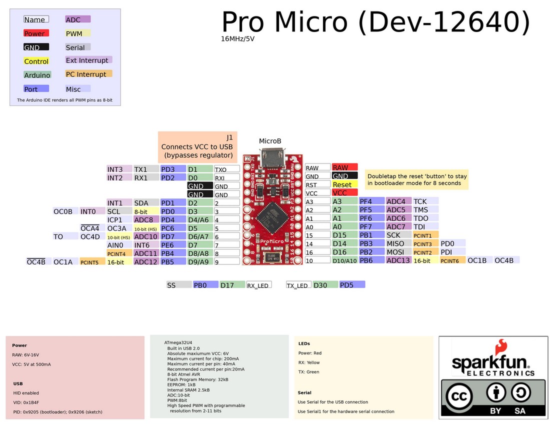
Part II: Protect your Arduino (ATmega32U4) board.
40mA per pin,
no more than 100mA for a single port,
PortB (pins 8,9,10,14,15,16) & PortE (pin 7), PortD (pins 0,1,2,3,4,6) are critical with 6-7 pins,
PortC is a single pin
and no more than 200mA for the whole board.
NO Button Mashing
For pins 8,9,10,14,15,16 of PortB and pin 7 of PortE if you added a 330Ω resistor in series,
it will cap each to 15.2mA or total of 106.4mA but I use touch pads, TTP223, on pins 14 & 16.
The TTP223 chip is capable of Sink Current IOL = 8mA, so, 15.2 x 5 + 8 x 2 = 92mA.
For pins 0,1,2,3 of PortD which in software handles spinner/trackball X & Y axes
thru A/B interrupts, there is a larger risk of overloading port limits.
Device may have each A/B pin pulled low for extend periods.
A 390Ω resistor in series will cap each to 12.8mA or total of 51.3mA and
pins 4 & 6 with a 330Ω resistor in series will add another 30.3mA for a 81.6mA total.
These precautions will result in a longer life of the MCU internal circuits.
A Spinner using pins 2 & 3 with two buttons A & B with Start(Player) & Select(Coin) pins 5, 7, 8 & 9
should never have issues as load is spread across four Ports B, C, D & E.
The more buttons or functions you add, higher the risk to overloading the MCU limits.
Atmel ATmega16U3/ATmega32U4 excerpt
As in life, you usually find out info too late, I retro-fitted the eight buttons with resistors on the ground side using either 390Ω or 150Ω + 220Ω = 370Ω.
Isollated group of Coin & Play buttons - 5V / 390Ω = 12.8mA x 5V = 64.1 mW x 2 = 128.2mW which is under ¼W resistor rating.
Main group of A, B, X, Y, L, R buttons, top set of X, Y, L and bottom set of A, B, R with each set using 150Ω and later combined in series to 220Ω.
Each resistor will have a portion of voltage drop through it from 5V total but flow the total current of 5V / (150Ω + 220Ω) = 13.5mA.
V x A = (150Ω / (150Ω + 220Ω)) x 5V x 13.5mA = 27.4mW x 3 = 80.1mW, top/bottom 150Ω resistors under ¼W resistor rating.
V x A = (220Ω / (150Ω + 220Ω)) x 5V x 13.5mA = 40.1mW x 2 = 80.3mW, series 220Ω resistor under ¼W resistor rating.
If you are using any LED buttons source cathode ground before any resistor(s).