Arcade-Trackball
Arcade Trackball - based off Spinner version 2
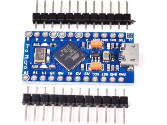
Using an Arduino Pro Micro - DIY Trackball Controller
At sub $10 USD, it is a substitute to Ultimarc’s U-HID Nano @ $35 + shipping - You do the HID device coding…
Code to follow: New additional y-axis interrupt & movement processing for both x/y axes handling.
Oct. 12/20: Code now availble, see extra pictures of finished Trackball box.
Dec. 16/20: Added code for x-axis disable (Golf game driver - no hook/slice cheat).
Dec. 16/20: Uploaded new code for override Joystick directions mod (using buttons for menu).
Jan. 15/21: Uploaded new code for Trackball six colour rotation using a RGB 5050 LED Strip.
(Use of programmer is required to unprogram fuse bit, JTAGEN = 1)
Jan. 26/21: Uploaded new code for Mouse only Trackball operation. Note: all buttons can be inactivated for Trackball-Only operation.
Feb. 19/21: Updated code for Trackball six colour RGB 5050 LED Strip.
Dec. 30/22: Uploaded new code for Mouse vari-SpinSpeed Trackball (can be used in MiSTer FPGA Cores where device too sensitive)
This project uses an Arduino Pro Micro clone, arcade trackball(Atari/Happ style), with 8 buttons (up to 10) for use with MAME or any other emulator which can use x/y axes of mouse device as a trackball controller. Code should work on any board using an ATmega32U4 as long as port pins are mapped to same “digital pins” as Pro Micro.
To construct, you will need an older non-PS/2 style trackball which can operate at 5v along with your momentary switches affixed to an Arduino micro controller.
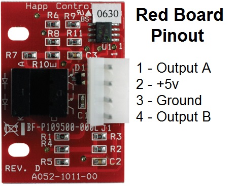
This trackball, RA-TRACKBALL-2, uses red Opto boards, A052-1011-00, and not a green PS/2 Opto board pair. The green board pair can suffer from backspin. USB+PS2 Mouse MCU controller, HT82M98A, runs at 6 MHz and historically experience dropped signals of Quadrature transistions during rapid movement. Coding your own HID controller with ATmega32U4 is one reason why I used RA-TRACKBALL-2 Trackball, plus it is cheaper. It is unknown if a Jamma 60-in-1 (6-pin header) style trackball uses quadrature rotary encoder pulses for x/y axes like the Game Elf Jamma 138/276/352/485/619/1162-in-1, etc. (10-pin header/dual player) boards; or the board outputs PS/2 (DIR/CLK) protocol. AliExpress does show a Jamma 60-in-1 board with trackball using 6-pin header & 10-pin header harness, but would require a closer look at encoder boards.
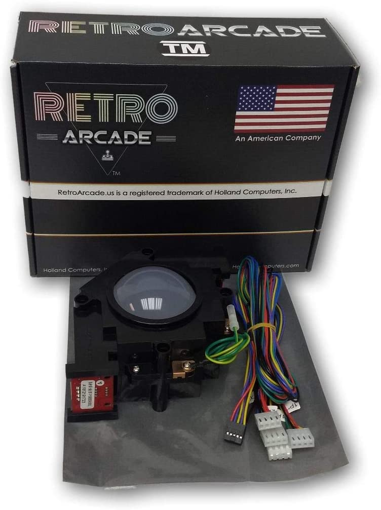
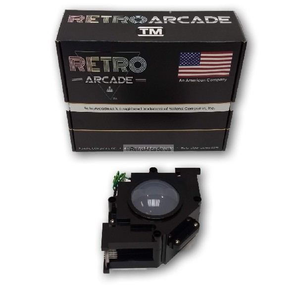
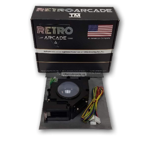
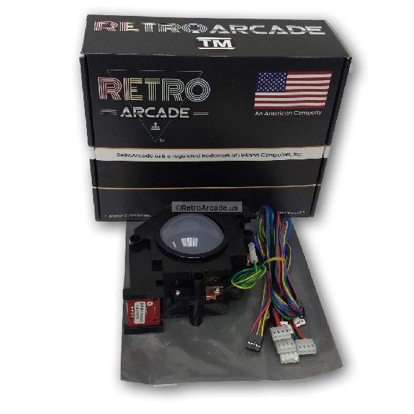
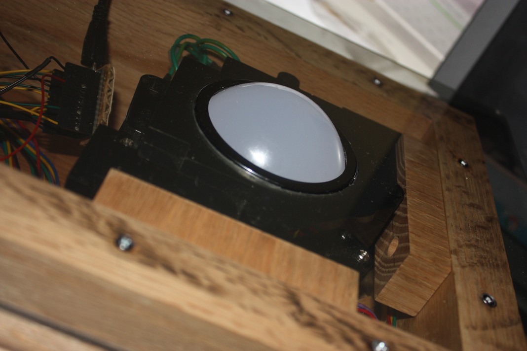
TrackBall used (clone of SuzoHapp style trackball by RetroArcade.us)
RA-TRACKBALL No Harness,
RA-TRACKBALL-1 Jamma 60-in-1 Harness,
RA-TRACKBALL-2 Game Elf 412-in-1 Harness
ATmega32U4 used (clone of SparkFun Pro Micro)
How does a Trackball work
Simple explaination, a trackball is a dual digital rotary encoder with each axis, x or y, acting as quadrature input device or spinner. Instead of turning spinner knob directly, a ball contacts either/both roller that twists/turns individual axis encoder. A rotary encoder have dual A & B phases with low/high or high/low signal transistions. One phase will always follow another phase due to a physical offset with a complete cycle producing 4 pulses (AL→H, BL→H, AH→L, BH→L, repeat) or quadrature signal. Only two temperal AB states (before/after) require capturing of AB or BA signals to decipher eight valid sequences out of sixteen total combinations. Two sets of four will indicate clockwise or counter-clockwise movement. A signal of AA, BB or similar will suggest invalid transitions or bounce states and should be ignored.
clockwise (AL→H, BL→H, AH→L, BH→L)
AL→H : ALBLAHBL, BL→H : AHBLAHBH,
AH→L : AHBHALBH, BH→L : ALBHALBL
counter-clockwise (BL→H, AL→H, BH→L, AH→L)
BL→H : ALBLALBH, AL→H : ALBHAHBH,
BH→L : AHBHAHBL, AH→L : AHBLALBL
You will need Arduino joystick library at: https://github.com/MHeironimus/ArduinoJoystickLibrary
Matthew Heironimus joystick code: Joystick.cpp &
Joystick.h or
Download: master.zip
In Arduino IDE:
- Select Sketch
- Include Library
- Add .ZIP Library…
- Browse to downloaded ZIP file
- Click Open
The Joystick library’s examples will now appear under File > Examples > Joystick.
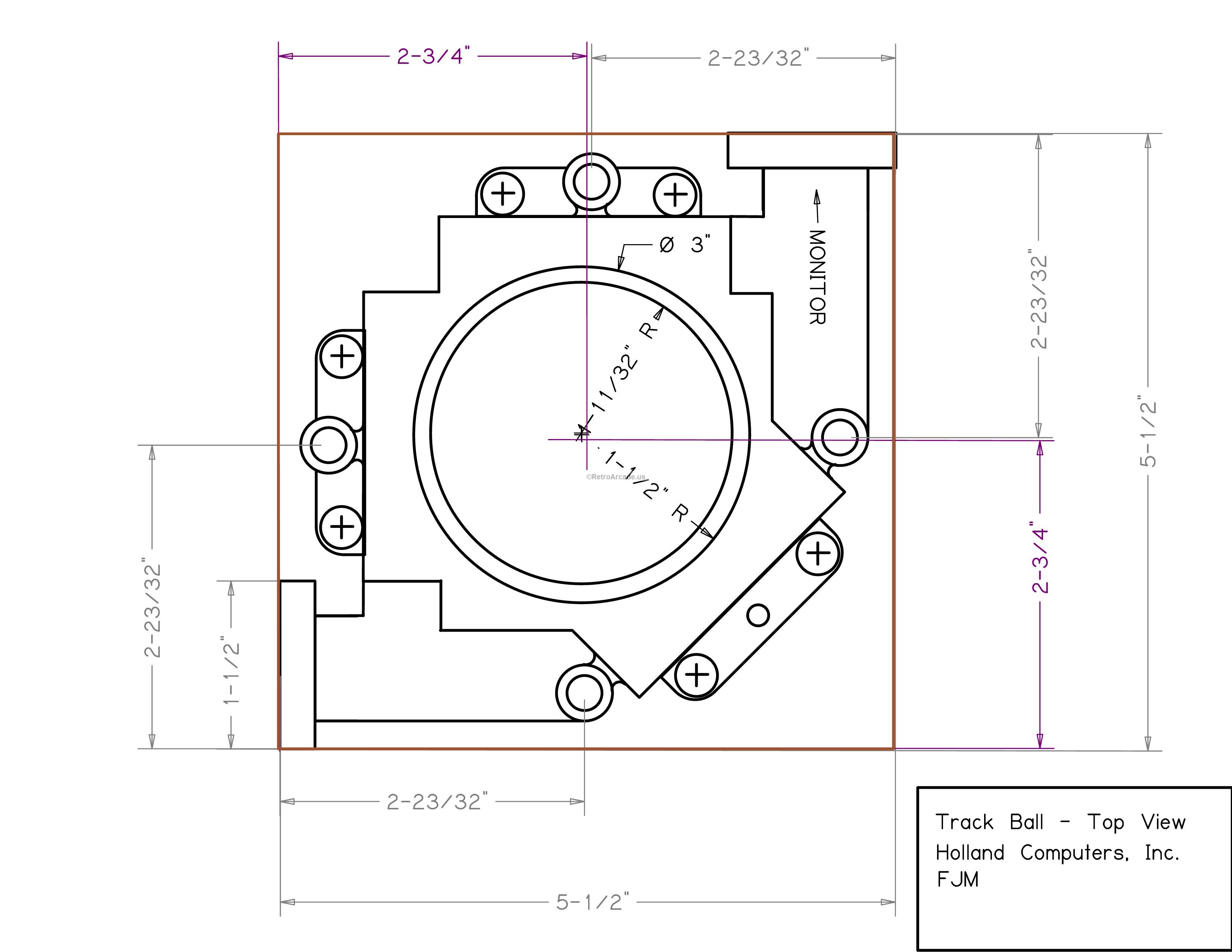
This device will be detected as both mouse and gamepad/joystick. RetroPie requires joystick X/Y axes to be declared in library call for controller buttons to be detected. Just center X/Y axes in setup() and forget, later code versions use Button/Joystick override for RetroArch menu navigation. The trackball controls X & y axes which by default is mapped to the mouse in MAME (don’t forget to enable mouse in MAME under advanced options!). Buttons will work as regular gamepad/joystick buttons. Arcade 3” trackball rotates a 24 slot wheel with roller, gear ratio of about x7 (3.000”/0.425”) = 169.412 slots/rev or 677.65 pulses/rev. Hand movement of 9.42”/rev. Comparing movement to my spinner (600p/r or 2400 pulses/rev), movement is effectively half, but can be adjusted in software for micro controller.
Code uses Atmega32u4 ports directly because that’s faster (over x30) than using digitalRead/Write. No button debouncing is setup, but can be added depending on your hardware issues.
Extra info:
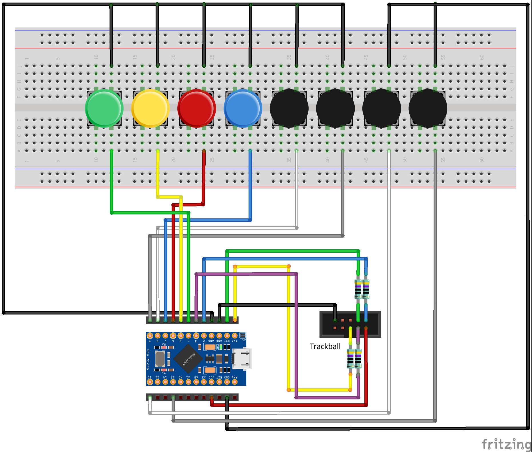
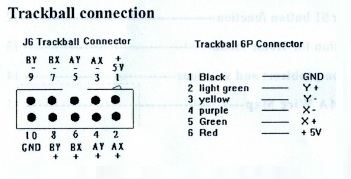
Wiring: See diagram, 2x5 pinout,
2x5 conn image (lower left Red-Purple-Yellow)
Vcc (+5V) and Gnd output wires red and black
Trackball A(XB), B(XA), C(YA) & D(YB) output wires blue, purple, yellow and green.
Colours match generic Game Elf 10 pin wire harness, Suzo/Happ 6 pin wire harness uses same colours but flip-flop X & Y axes.
Note: resistor used in series to limit current around 10mA (390Ω - 470Ω).
Red Opto boards have LMC662CM (Dual Op Amp) acting as output buffer with 21-22mA limits
Buttons 1-6, plus 9-select(coin), and 10-start(player)
| Pin | Data | Button/wire | Code | 2x5 Conn |
|---|---|---|---|---|
| 0 | D1 | YA trackball - Yellow | PD3/PinC | Ay- (5) |
| 1 | D0 | YB trackball - Green | PD2/PinD | Ay+ (4) |
| 2 | D2 | XB trackball - Blue | PD1/PinA | Ax+ (2) |
| 3 | D3 | XA trackball - Purple | PD0/PinB | Ax- (3) |
| 4 | D4 | Button 1 - X | ||
| 5 | D5 | Button 2 - A | ||
| 6 | D6 | Button 3 - B | ||
| 7 | D7 | Button 4 - Y | ||
| 8 | D8 | Button 5 - L | ||
| 9 | D9 | Button 6 - R | ||
| 10 | D10 | Button 9 - Select | ||
| 15 | D15 | Button 10 - Start | ||
| Gnd | Gnd - Black | Gnd (10) | ||
| Vcc | +5v - Red | +5v (1) | ||
| 16 | D16 | Switch: X-Axis Opt. | ||
| 14 | D14 | Switch: Joystick Opt. | ||
| A0 | F7/D23 | - - - | ||
| A1 | F6/D22 | RGB BlueOut Opt. | ||
| A2 | F5/D21 | RGB GreenOut Opt. | ||
| A3 | F4/D20 | RGB RedOut Opt. |
I believe the trackball encoder A/B output is reversed as you move the ball and not the roller directly. The code has been tested and trackball moves in the proper direction, so, the code was left as is. This Opto encoder board is also used for steerwheel devices.
I am using Xbox A/B, X/Y configuration, Nintendo protocol is B/A, Y/X reversed controls (Japanese cultural differences).
You can assign buttons to any assignment in RetroArch but it is best to pick a consistent pattern across all controllers to avoid confusion.
Some trouble shooting with your controller
The Code:
There are five versions of code: Pick your code to use
- Standard Mouse and Joystick buttons version
- Special Mouse only version with & without Mouse buttons - no Joystick buttons
- Standard Mouse and Joystick buttons version - mod Joystick directions (use buttons for menu)
- Standard Mouse and Joystick buttons version - mod RGB Trackball and Joystick directions
- Trackball_8-Button-mod-rgb.ino 1. 2. Update is available… parts arrived & tested.
- Trackball_8-Button-mod-rgb.ino 1. 2. Update is available… parts arrived & tested.
- Special Mouse vari–SpinSpeed version - 6 +2 +1 buttons
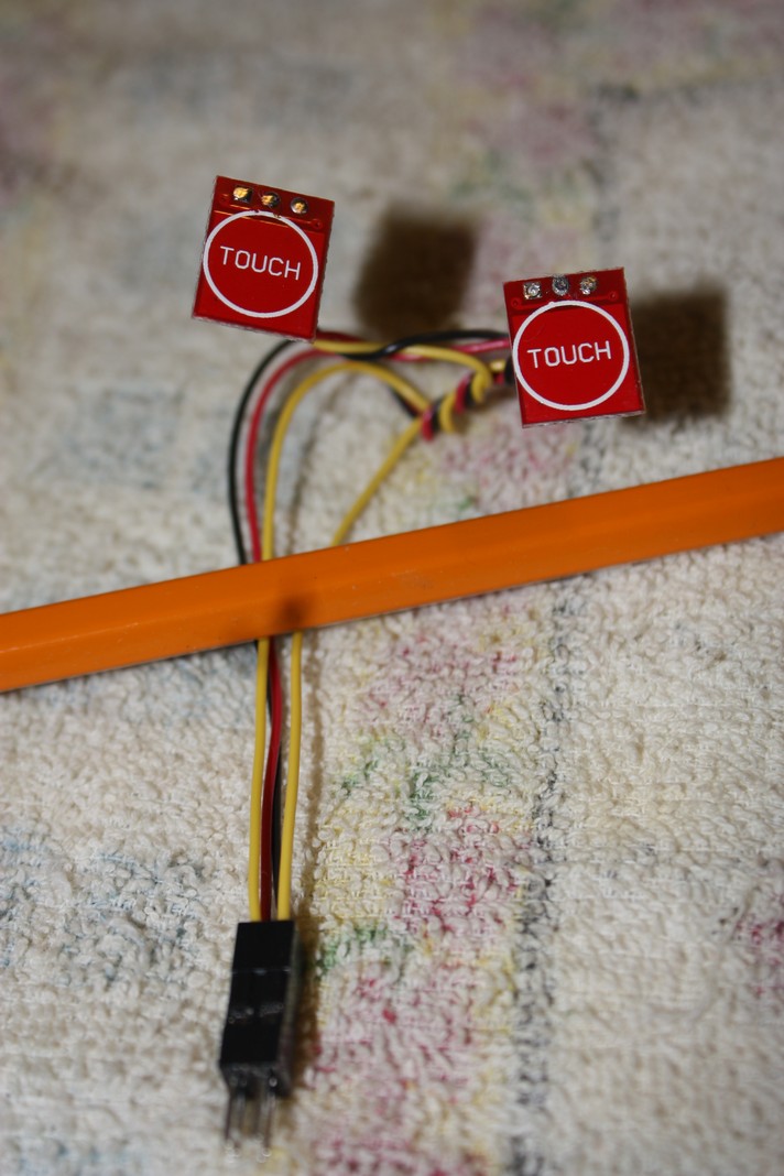
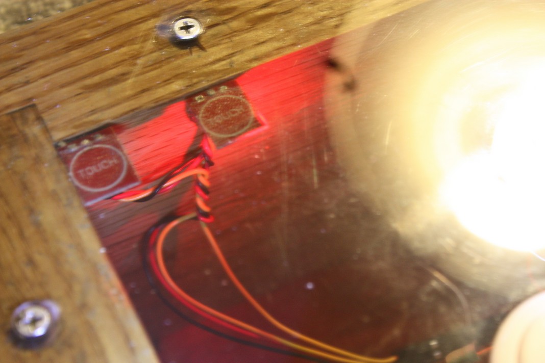
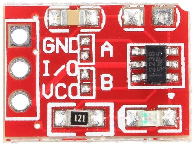
1. Used two TTP223 Capacitive Touch switches to control special functions: the
“Touch Switches” and
“Touch in Box”
Note: Invert the Touch I/O state by shorting contact A to Vcc, and/or contact B to activate on/off toggle mode.
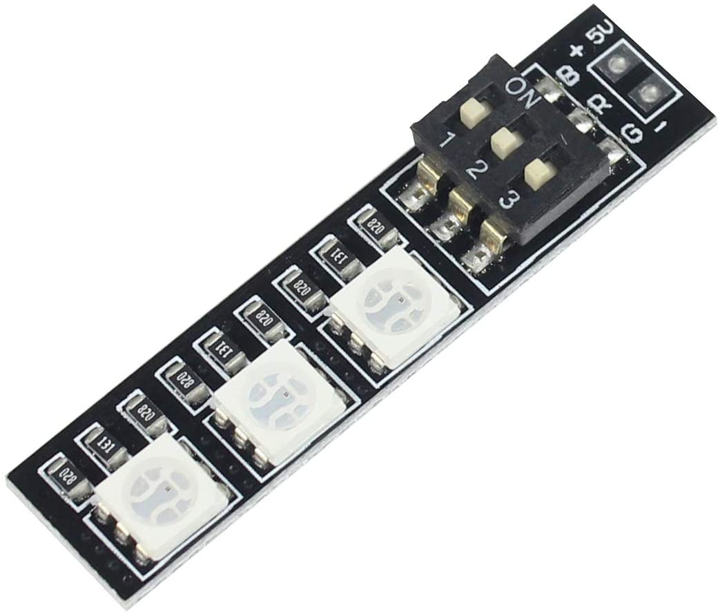
2. Trackball colour rotation using a RGB 5050 LED Strip and
PORTF bits 4-6 set to output (requires fuse bit JTAGEN=1 be disabled) to control each colour LED (Red, Green Blue).
Proceed at own risk.
You may not require an ISP Programmer, if fuse bit JTAGEN=1 has been factory set. You will need to validate with LED and resistor anyway.
Use caution when reprograming Fuse bits (L-FF, H-D8, E-C8) & Bootloader as incorrect settings may brick your microcontroller.
Extra circuitry likely required to handle RGB LED current, microcontroller has 40mA current limits per bit without damaging Port output.
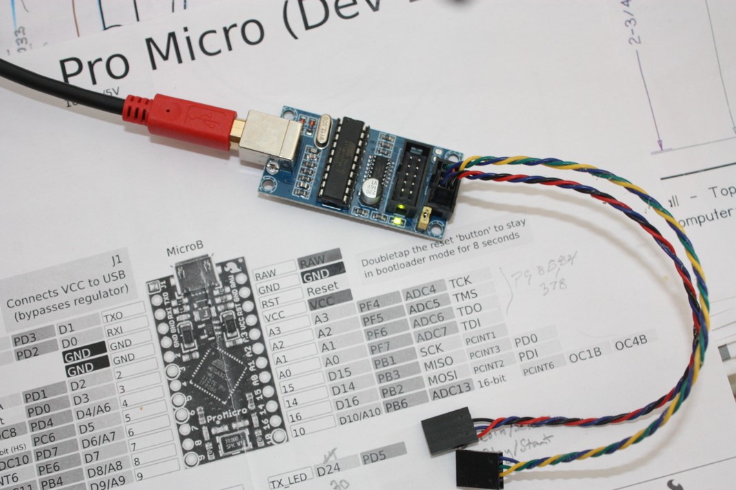
Inverting MOSFET circuit (Common Anode),
Inverting MOSFET circuit (Common Cathode) &
USBtinyISP Programmer & DIY Harness
Note: using MOSFETs
-ca.jpg)
-cc.jpg)
How I Changed my Pro Micro Fuse bits
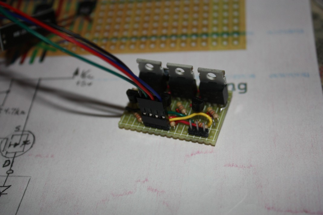
My LED driver board:
required multiple redesigns due to 5050RGB LED strip board positive anode side switches, requiring use of P-Channel MOSFET. I also had issues sourcing some components locally.
Here is my circuit x3 and required MOSFET driver board to switch each Red, Green, Blue LED segment (66mA @ 5V is too much for direct micro-controller driving).
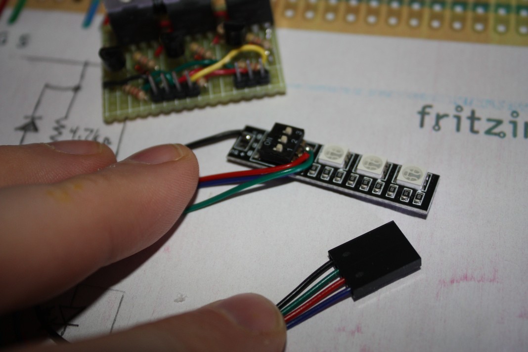
5050RGB circuit & pre-board,
5050RGB wired LED strip,
5050RGB finished driver board
starting RGB White then dims from camera’s auto-exposure (colours may differ in-person)
➙White to Red, Yellow, Green, Cyan, Blue, Magenta…
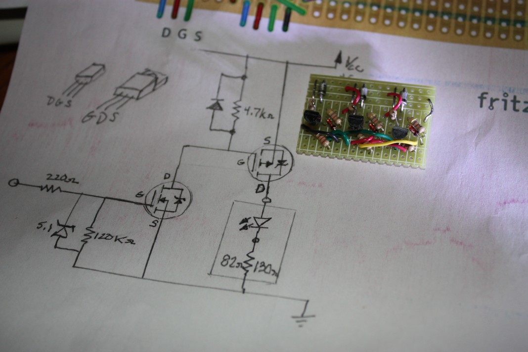
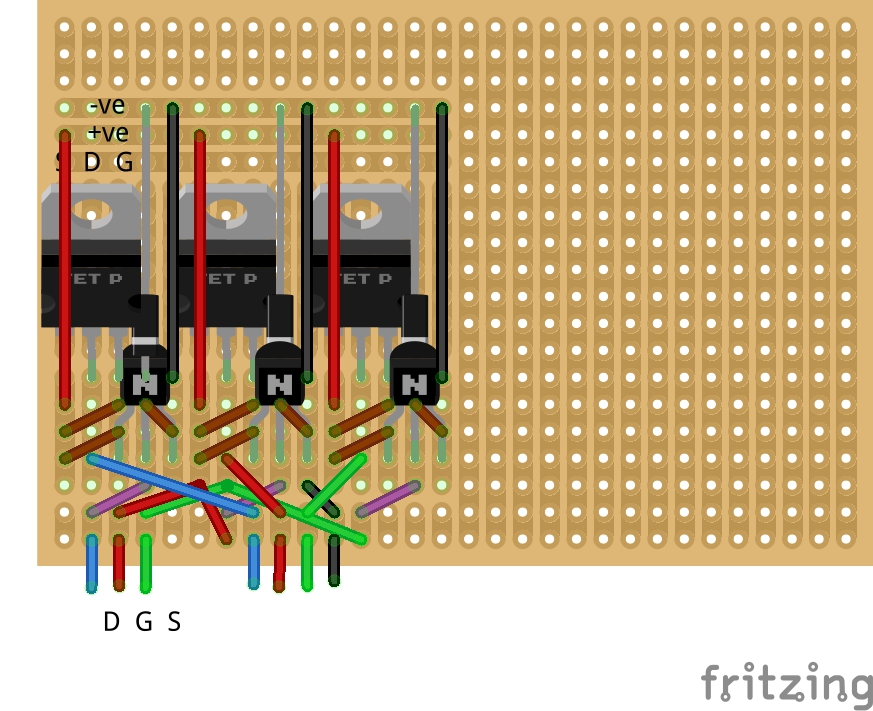
Here is the circuit design I used for 5050RGB strip:
My circuit and,
DIY circuit layout
Components were sourced locally, P-MOSFET is overkill at 3.0A.
(Note: Layout displays solder side & components located on other side;
Brown and Purple links correspond to passive components)
-cc-3.jpg)
Other issues related to excessive current pull from added new Trackball RGB LEDs, required a separate USB Port/cable to be used to power close to 200mA current pull along with original USB cable to supply 100mA for micro-controller/switches/buttons and dual quadrature encoder boards from trackball. Trackball voltages at encoder boards were floating around 4.5V and operating without issues; however, when RGB LEDS were added voltage dropped to low 3V range triggering false signal pulses to the micro-controlller. A heavy duty USB cable capable of carrying current 3A or over (24AWG) may have solved the problem, but I just used a separate USB cable to supply the new needs of the RGB LEDs. Note: you must tie grounds(negative) together for equal Gnd levels; DO NOT tie +5v together.
Extra expenses:
Dupont connectors 2.54mm pitch JST SM kit (requires special crimper)
or female Dupont pre-wired bundles with spare wire 24-28AWG (stranded wire for flexiblity),
Sanwa - 2.8mm(0.110”) or Suzo-Happ - 4.8mm(0.187”) female spade crimp connectors for arcade button ends,
Special Trackball lighting with RGB 5050 LED Strip, and
Special function switches with TTP223 Capacitive Touch Switch
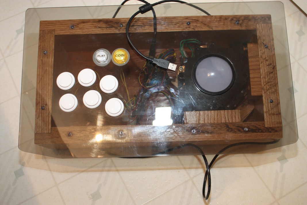
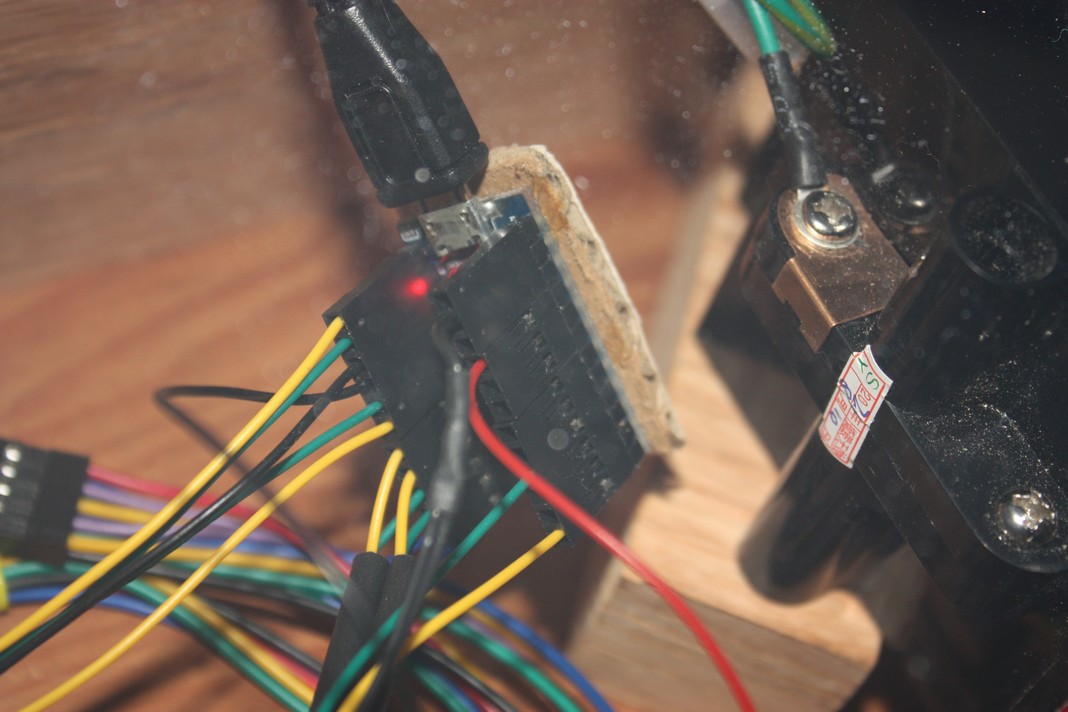
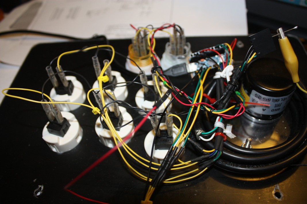
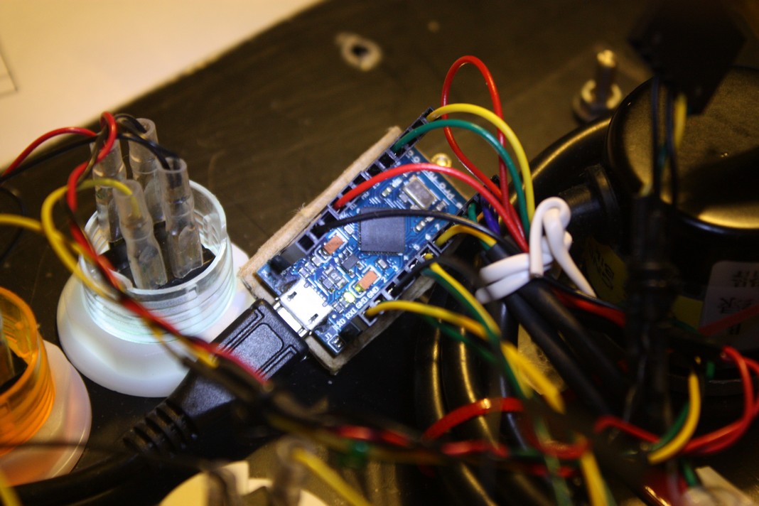
For the more observant in pictures
“Inside Spaghetti” and
“Arduino Beauty Shot”
there’s an extra wire harness and aligator clip hooking to Gnd. TX0 & RX1 are wired to the y-axis of a proto-type Trackball setup. Arduino code has been modified, tested and confirmed to work. No stutter or lag as using only USB protocol to RetroPie. No PS/2 Protocol overhead. I will be working on enclosure to finish new controller for games like Centipede, Marble Madness, Crystal Castles, and others.
Video:
Trackball in Action playing Centipede
Trackball in Action playing Crystal Castles
 RetroPie laggy trackball issues
More pictures:
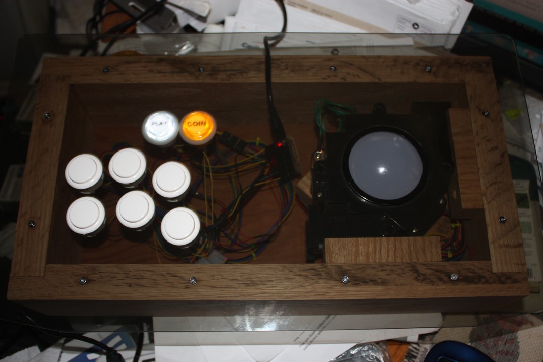
The assembled pictures before adding clear finish to antique oak wood box
“See-thru-Top”,
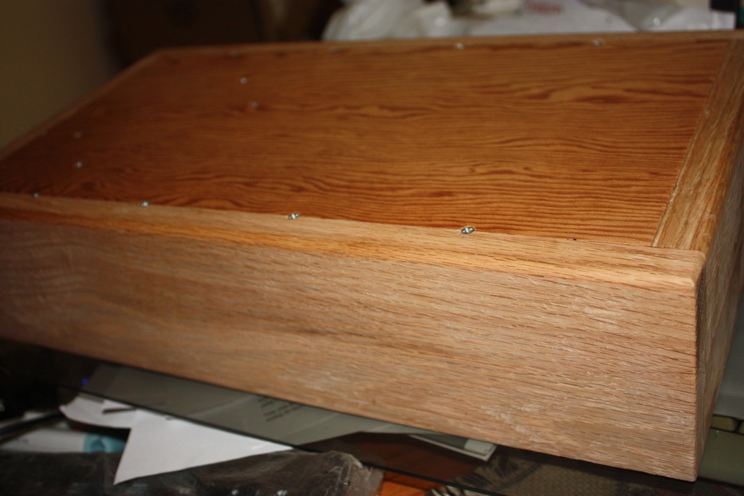
“Bottom-side”,
“ATmega32U4 wired inside”,
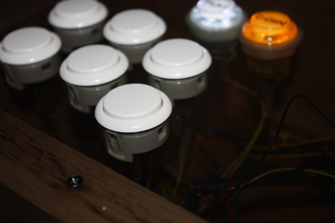
“Buttons”,
“Trackball”.
The top, I used tinted Polycarbonate sheet (0.120” thick) found at a local surplus store and bottom from wood sitting in my parents basement from early 60’s sourced from Stelco for handling steel. I later found out the wood was very dense, hard oak 100 to 120 years old from sapling. I snapped a few #4 screws while assembling which staled progress. Bottom panel is 3/16” - 1/4” plywood insert.
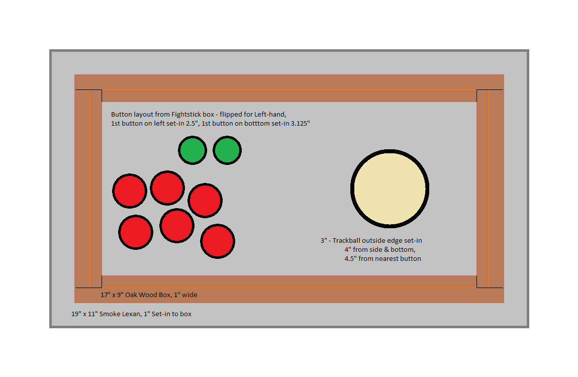
The Box:
The wood box measures 17” x 9” x 3⅞” in size, with a 19” x 11” Lexan top - Trackball box dimensions;
wood sides have 7/16” rabbet butt joints glued, and 7/16” rabbet along inside bottom edge to allow 15⅞” x 7⅞” plywood panel to recess in flush. The outside bottom edge has a ¼ round routered edge.
Physical dimensions of Trackball are shimmed by four wooden blocks on right side, bottom side, and two on the box bottom. Block dimensions will vary with your own inside/outside box dimensions; leave space under ball to allow lighting and “Dust Bunny” particles to fall through. Please note: that if you compare idealized dimensions to what can be seen in finished pictures; it deviates somewhat to avoid an extended masochistic hand planing session leaving ones arms as chipper as a snail on a sloth.