Arcade-Spinner
Arcade Spinner version 2 - based off earlier Spinner
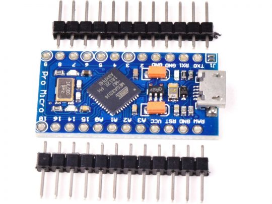
Using an Arduino Pro Micro - DIY Spinner Controller, plus affordable Rotary Encoder
I decided to post my version of code including ‘compiler control directive code’ for rotary encoder (spinner) movement, and addition of extra buttons that a standard fight box had pre-configured cut holes (6-30mm & 2-24mm). The code works with Arduino Pro Micro style boards made by clone manufacturers using the Atmel ATmega32U4 MCU with native USB HID support. The original 2019 code was posted by ‘jmtw000’. In time, Joe’s code mutated to be used with Arduino Micro, Adafruit Itsy Bitsy, and other style boards that have extra pinouts unused by status LEDs. You will not find pins 11, 12, and 13 (also SS, 3V, Aref, A4, A5 & 2-NCs) on an Arduino Pro Micro board (length saving of 0.66”) but pins 14, 15, and 16 (MISO/SCLK/MOSI). They appear to be mapped to different ATMega Portx bits.
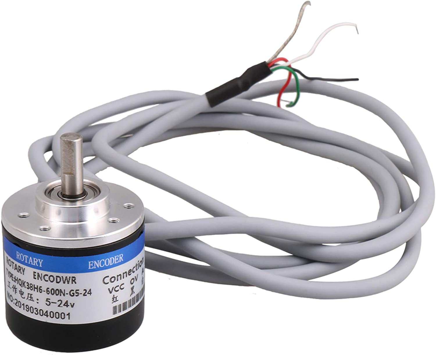
A simplified chinese knock-off Rotary Encoder (Optical version) of an industrial Omron E6B2-CWZ6C encoder costing hundreds can be obtained from online stores around $30. Investigate purchase wisely as quality and standardization may vary. Ditto for selection of Arduino Pro Micro boards compatible to Sparkfun board, making sure you get 5V/16MHz version with pre-installed bootloader and pin headers. An USB 2.0 type A-to-MicroB cable of 3 to 6 feet will be needed, and not a two conductor charge cable. Note: There seems to be two common boot loaders used on clone Pro Micro boards, SparkFun Caterina Pro Micro version and Arduino Leonardo version.
Here are some brandname Arduino boards:
- Arduino Micro by Arduino Srl & Adafruit
- Arduino Micro, Adafruit ItsyBitsy
- Arduino Pro Micro by SparkFun
.jpg)
.jpg)
Sept. 5/20: Uploaded my version of code from 2019; sourced June 27/19 and modified/optimized/bug fixed during summer 2019.
Sept. 11/20: Uploaded revised code to allow switching of Spinner’s X & Y axis - mod axisFlip directive to setup special button of choice.
Dec. 11/20: Uploaded new code for Mouse only Spinner operation. Note: all buttons can be inactivated for Spinner-Only operation.
Dec. 16/20: Uploaded new code for override Joystick directions mod (using buttons for menu)
Dec. 11/22: Uploaded new code for Mouse only Spinner operation. (Stand alone Arcade Spinner - no LCR mouse or joystick buttons)
Dec. 20/22: Uploaded new code for Mouse vari-SpinSpeed Spinner (can be used in MiSTer FPGA Cores where device too sensitive)
Nov. 2023: Uploaded debug code to diagnose wire connections (Need +5V/Gnd/A or B for error message, power/voltage dropout issues & non-movement)
July 13/25: Uploaded new code for Mouse only Dual Spinner operation. (Stand alone Arcade Spinners - no LCR mouse or joystick buttons)
TBD. 2025: Uploaded new code for Rotary Encoders with odd PPR values - Ratio’d (fixed) Input-to-Output Spinners hybrid of vari-SpinSpeed code
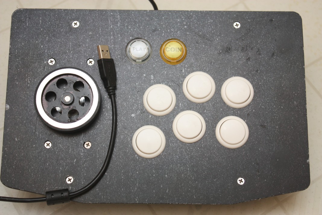
This project uses an Arduino Pro Micro clone, arcade spinner, with 8 buttons (up to 10). It maybe used with MAME or any other emulator which can use the mouse X-axis as a paddle/spinner controller. Code should work on any board using an ATmega32U4 as long as port pins are mapped to same “digital pins” as Pro Micro. The DIY spinner was created as a cheaper alternative to commercially available devices. It works well with ball and paddle games, like Arkanoid, ever popular shooter Tempest, driving game like Pitstop and many other non-joystick controller games.
To construct this, you will need a 2-phase rotary encoder which can operate at 5v along with your momentary switches affixed to an Arduino micro-controller like SparkFun Pro Micro - 5V version or similar clone.
Rotary encoder used
1
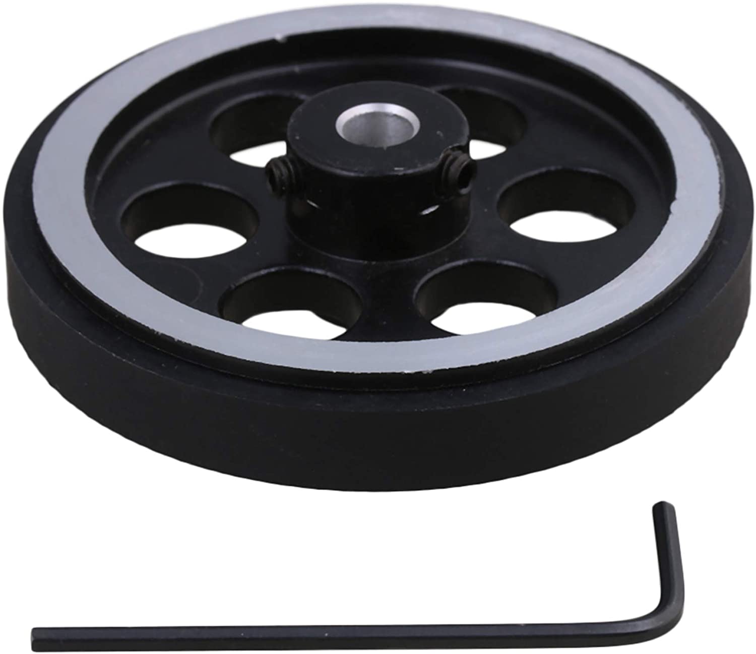
2 (600 pulses/rev quadrature optical encoder = 2400 pulse spinner)
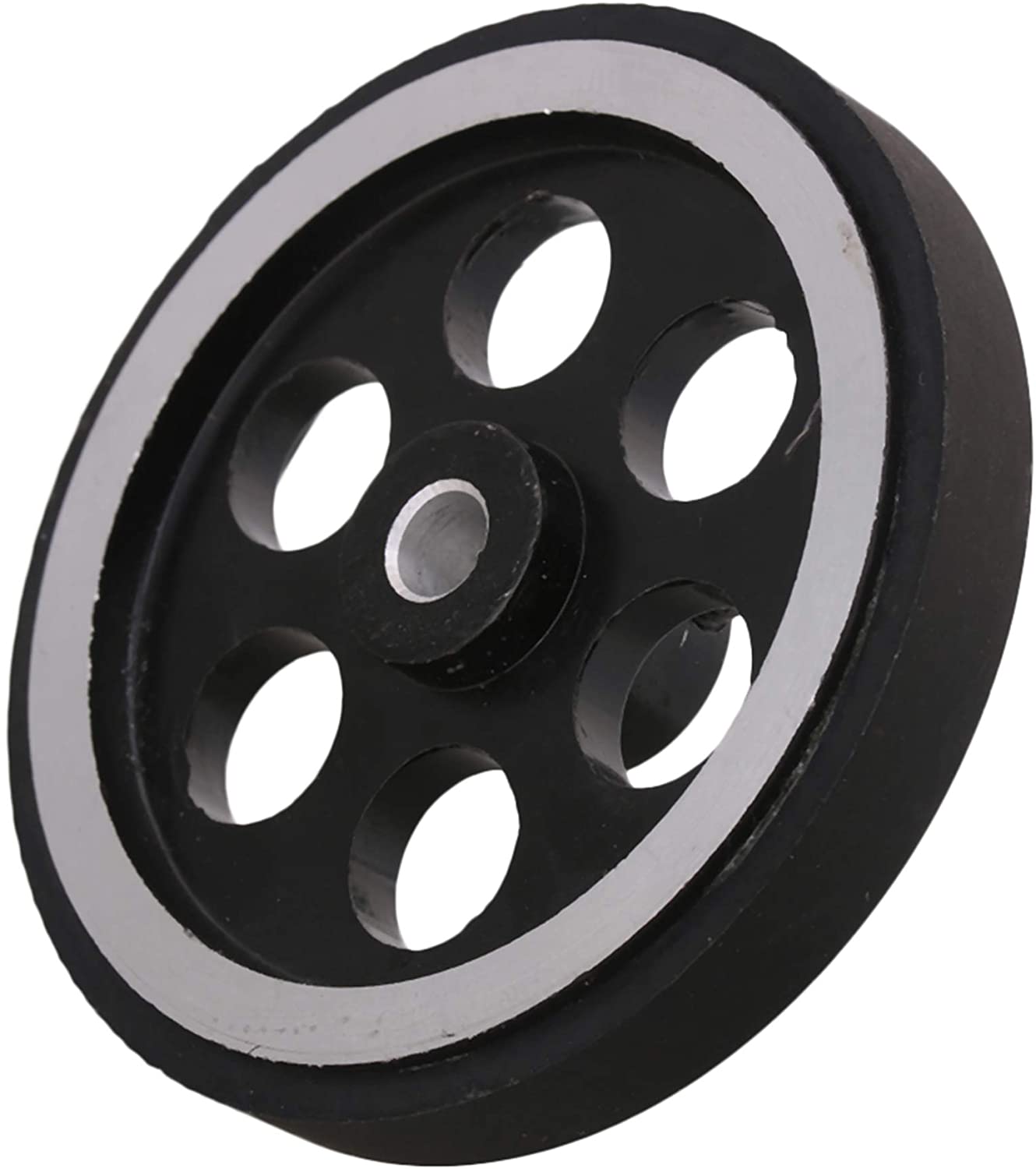
Wheel used
1
2 (Generous 2.5” dia. aluminum/rubber weighted spinner, better than 1” guitar knobs)
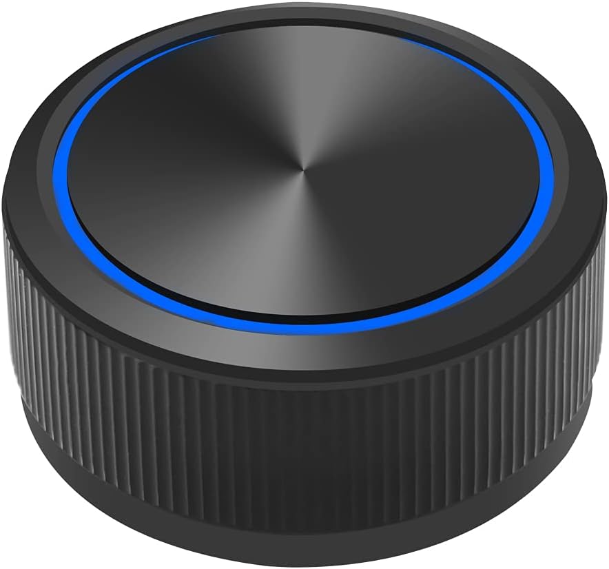
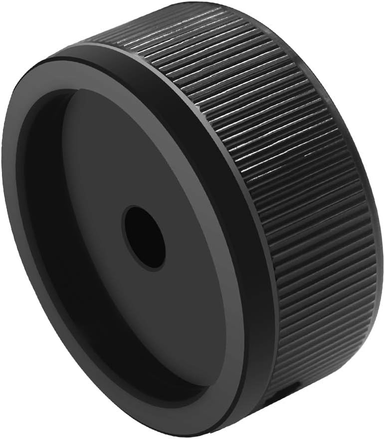
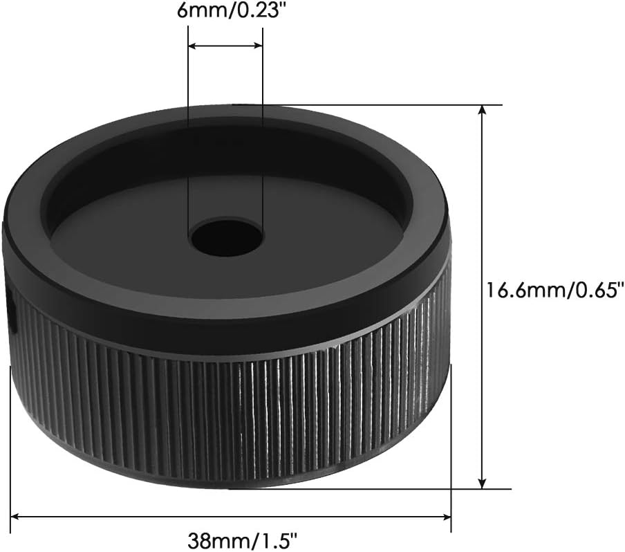
Alternate Knob
1
2
3 (1.5” dia. aluminum 32g spinner knob for Breakout/Arkanoid)
ATmega32U4 used
1 (clone of SparkFun Pro Micro)
Arcade Box used
1 (convenient plastic fightstick box)
How does a Spinner work
Simple explaination, a spinner is a digital rotary encoder of either x or y axis, acting as quadrature input device. Turning the spinner knob by hand directly twists/turns the rotary encoder. A rotary encoder have dual A & B phases with low/high or high/low signal transistions. One phase will always follow another phase due to a physical offset with a complete cycle producing 4 pulses (AL→H, BL→H, AH→L, BH→L, repeat) or quadrature signal. Only two temperal AB states (before/after) require capturing of AB or BA signals to decipher eight valid sequences out of sixteen total combinations. Two sets of four will indicate clockwise or counter-clockwise movement and bring about state machine logic. A signal of AA, BB or similar will suggest invalid transitions or bounce states and should be ignored.
clockwise (AL→H, BL→H, AH→L, BH→L)
AL→H : ALBLAHBL, BL→H : AHBLAHBH,
AH→L : AHBHALBH, BH→L : ALBHALBL
counter-clockwise (BL→H, AL→H, BH→L, AH→L)
BL→H : ALBLALBH, AL→H : ALBHAHBH,
BH→L : AHBHAHBL, AH→L : AHBLALBL
You will need Arduino joystick library at: https://github.com/MHeironimus/ArduinoJoystickLibrary
Matthew Heironimus joystick code: Joystick.cpp &
Joystick.h or
Download: master.zip
In Arduino IDE:
- Select Sketch
- Include Library
- Add .ZIP Library…
- Browse to downloaded ZIP file
- Click Open
The Joystick library’s examples will now appear under File > Examples > Joystick.
This device will be detected as both mouse and gamepad/joystick. RetroPie requires joystick X/Y axes to be declared in library call for controller buttons to be detected. Just center X/Y axes in setup() and forget, later code versions use Button/Joystick override for RetroArch menu navigation. The spinner controls X-axis which by default is mapped to the mouse/analog dial in MAME (don’t forget to enable mouse in MAME under advanced options!). Buttons will work as regular gamepad/joystick buttons. The spinner produces 2400 Quadrature pulses (transitions) from a 600ppr(pulse per revolution) encoder; that is excessive, so, the code halves the count to 1200. Code uses Atmega32u4 ports directly because that’s faster (over x30) than using digitalRead/Write. No button debouncing is setup, but can be added depending on your hardware issues.
Extra info:
Wiring: See diagram
Vcc (+5V) and Gnd, Spinner A & B rotary output wires red and green. see picture
I advise you double check Vcc(5-24v power) & Gnd wire colours as some chinese factories are colour blind.
DC Current per I/O Pin ………………………………. max 40.0 mA
DC Current VCC and GND Pins …………………. max 200.0 mA
Note: resistor used in series to limit current around 10mA - Pop goes the Triode
Different currents = 5V / RΩ → 22.7mA (220Ω), 18.5mA (270Ω), 15.2mA (330Ω), 12.8mA (390Ω), 10.6mA (470Ω)
Heed the manufacture’s warning (Atmel Corp. now Microchip) and never short a pin to Gnd or Vcc. It’s safer to limit unknown current flow.
I have used an USB meter that contradicts any major current change when input pins are pulled high internally by ATmega32U4 MCU and shorted to Gnd.
Using rotary encoder H38S360B, 5-24V {wiring: A-Red, B-Grn, Vcc-Wht, Gnd-Blk}
This rotary encoder was originally shipped in error with wrong specs of 360 ppr, resulting in sluggish/slower top spin.
| Wire | English | Chinese | Simplified |
|---|---|---|---|
| Vcc | White | 白色的 | 白色的 |
| Gnd | Black | 黑色的 | 黑色的 |
| A/2 | Red | 紅色的 | 红色的 |
| B/3 | Green | 綠色的 | 绿色的 |
| — | Coloured | 色的 |
Using rotary encoder HQK38H6-600N-G5-24 {Alternate wiring: A-Grn, B-Wht, Vcc-Red, Gnd-Blk}
Note: On Pro Micro, J1 may require solder short to bypass diode/regulator, so rotary encoder electronics receive full 5V USB source.
| Wire | English | Chinese | Simplified |
|---|---|---|---|
| Vcc | Red | 紅色的 | 红色的 |
| Gnd | Black | 黑色的 | 黑色的 |
| A/2 | White | 白色的 | 白色的 |
| B/3 | Green | 綠色的 | 绿色的 |
| — | Coloured | 色的 |
Buttons 1-6(turned CW ‘S-pattern’), plus 9-select(coin), and 10-start(player)
| Pin | Data | Button/wire | Code |
|---|---|---|---|
| 2 | D2 | XA spinner - see | PinA |
| 3 | D3 | XB spinner - above | PinB |
| 4 | D4 | Button 1 - X | |
| 5 | D5 | Button 2 - A | |
| 6 | D6 | Button 3 - B | |
| 7 | D7 | Button 4 - Y | |
| 8 | D8 | Button 5 - L | |
| 9 | D9 | Button 6 - R | |
| 10 | D10 | Button 9 - Select | |
| 15 | D15 | Button 10 - Start | |
| Gnd | Gnd - Black/Blk | ||
| Vcc | +5v - Red/see above | ||
| 16 | D16 | Switch: Axis Flip Opt. | |
| 14 | D14 | Switch: Joystick Opt. |
I am using Xbox A/B, X/Y configuration, Nintendo protocol is B/A, Y/X reversed controls. (Japanese cultural differences)
You can assign buttons to any assignment in RetroArch but it is best to pick a consistent pattern across all controllers to avoid confusion. I searched the web for button layout, picked an Xbox A/B, X/Y sideways ‘S-pattern’ starting at top left, yes a fluke.
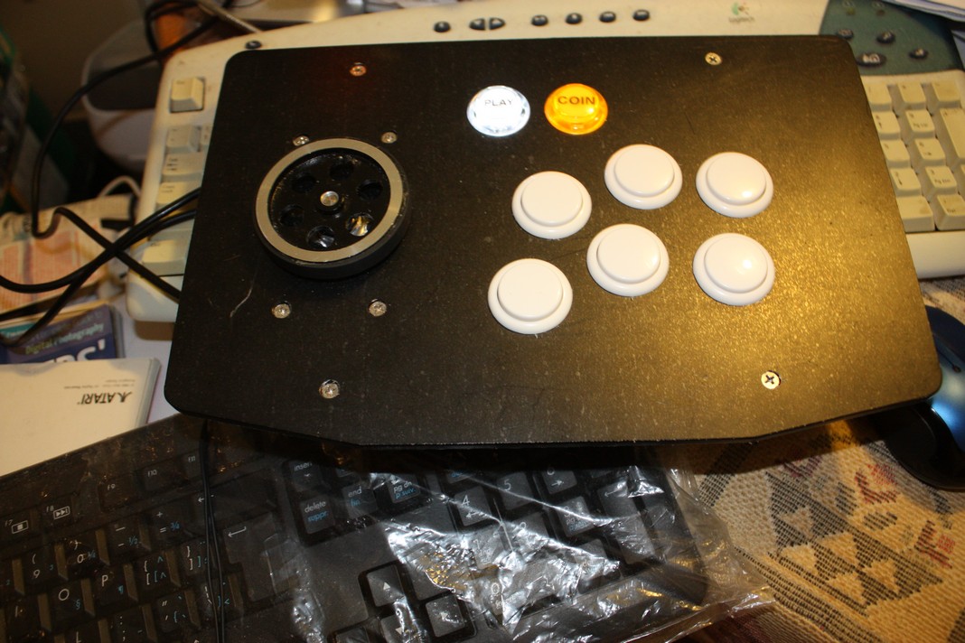
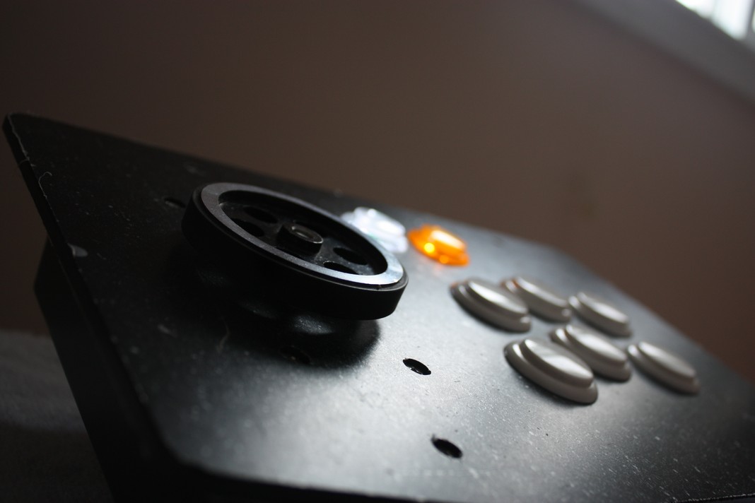
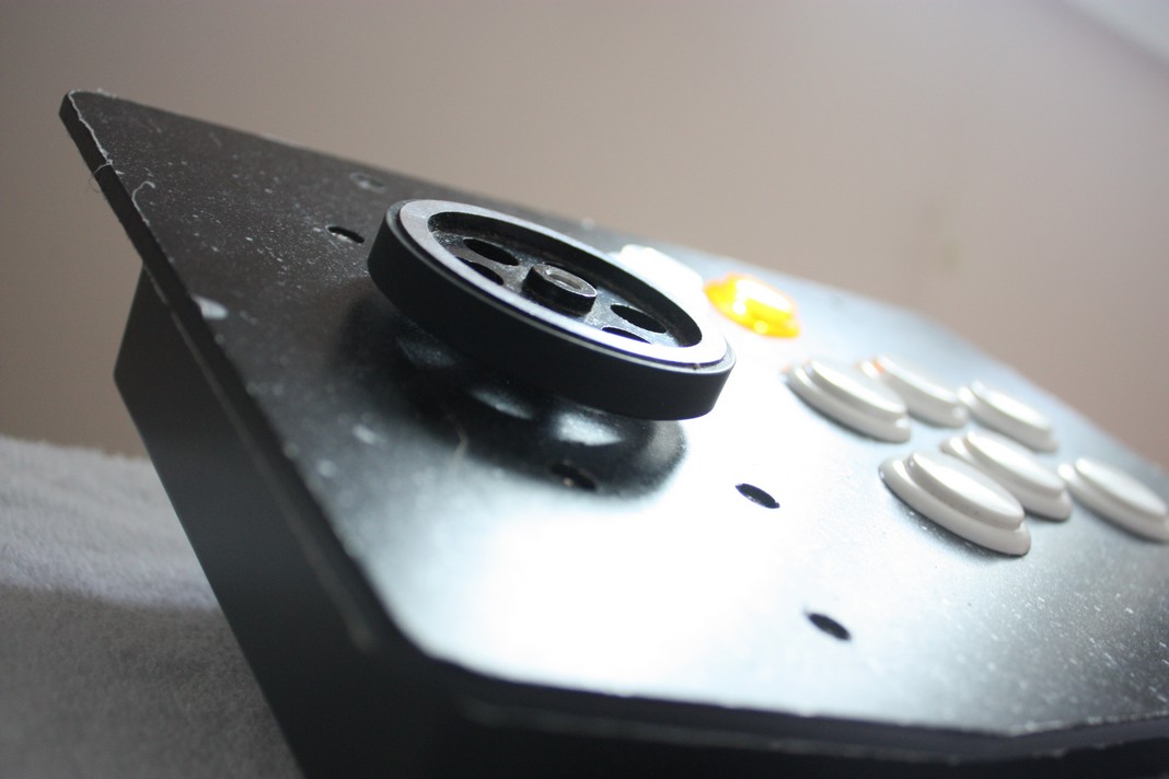
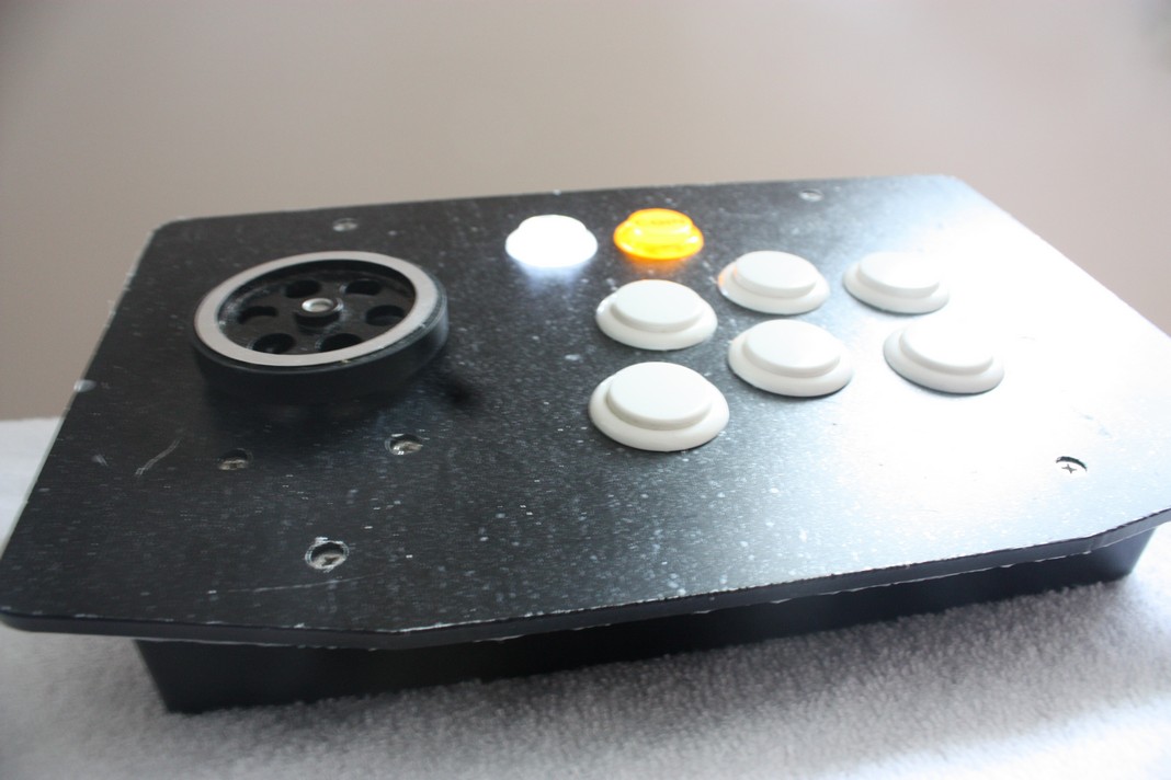
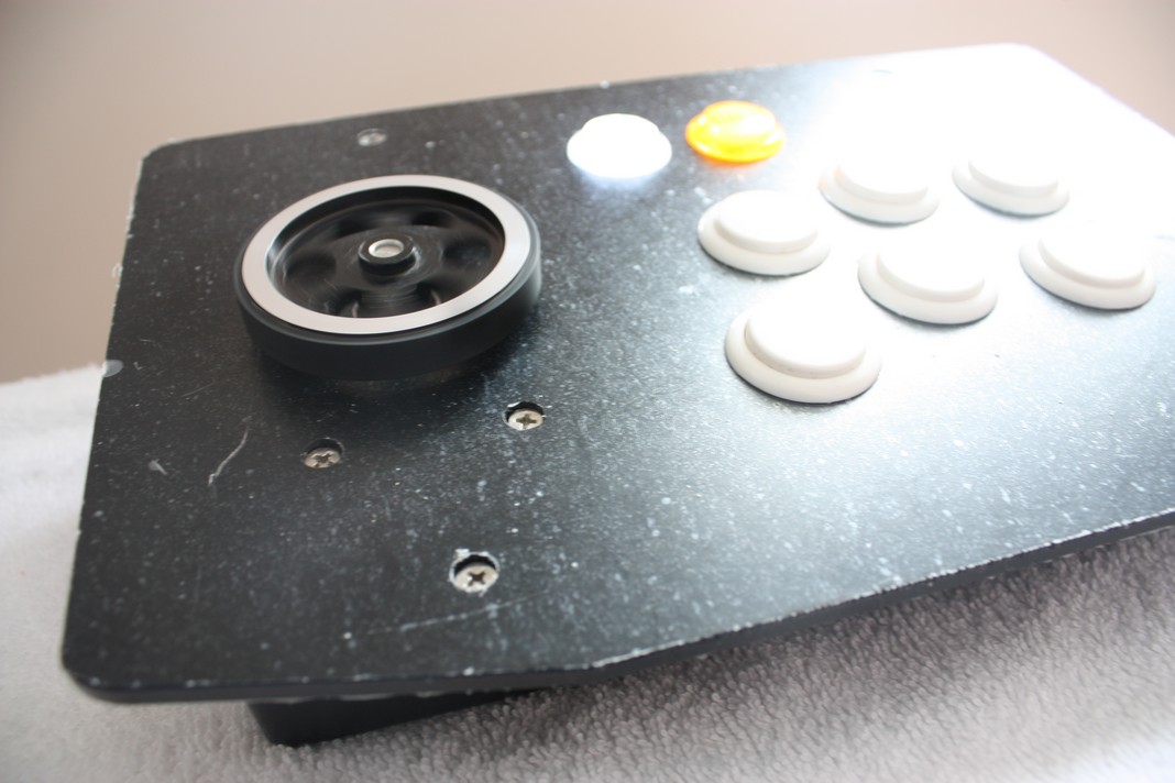
My Finished Spinner assembled within a DIY Fight Stick box.
Some trouble shooting with your controller
The Code:
There are five versions of code: Pick your code to use
- Standard Mouse and Joystick buttons version
- Special Mouse only version with & without Mouse buttons - no Joystick buttons
- Standard Mouse and Joystick buttons version - mod Joystick directions (use buttons for menu)
- Special Mouse only version - no buttons
- Special Dual Mouse only version - no buttons
- Special Mouse vari-SpinSpeed version - 6 +2 +1 buttons
- Standard Mouse and Joystick buttons version - Ratio (non 300/600/1200ppr but eg.360ppr)
- Special Debug code - Spinner Error with invalid Quadrature signals
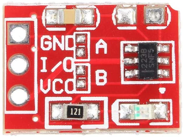
1. Use of TTP223 Capacitive Touch switches to control special functions: the
“Touch Switches”
Note: Invert the Touch I/O state by shorting contact A to Vcc, and/or contact B to activate on/off toggle mode.
Coin, Play & Special Buttons
Oops - I bricked my Bootloader!
Navigate to bottom of page - same title.
Extra expenses:
Dupont connectors 2.54mm pitch JST SM kit (requires special crimper)
or female Dupont pre-wired bundles (wire jumper) with spare wire 24-28AWG (stranded wire for flexiblity).
Sanwa - 2.8mm(0.110”) or Suzo-Happ - 4.8mm(0.187”) female spade crimp connectors for arcade button ends.
3 - 3x12mm Countersunk Machine Head Screws (sourced from Traxxas 2552 hobby parts); cut to length with dremel; uses same Allen wrench as grub screw with noted wheel.
Lexan sheet 0.060” thick, size 95x53mm(3.75x2.1”) or aluminum/steel sheet cut to same size of Sanwa JLF-P1 mounting plate. I don’t recommend using joystick plate as holes are located at 90° and rotary encoder mounts at 120° (28-30mm dia. M3 mounts with 20mm dia. raised bearing hub).
Clear Lexan makes visibility easier for fabrication.
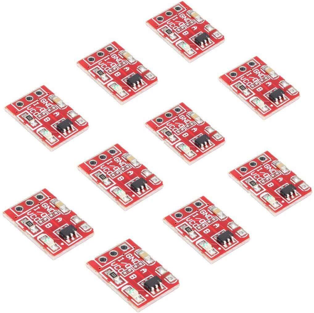
Special function switches with TTP223 Capacitive Touch Switch
1
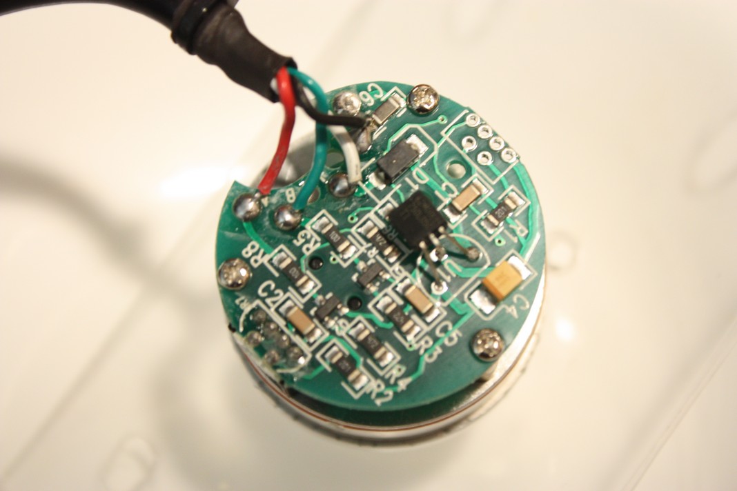
For the more observant in pictures “Inside Spaghetti” and “Arduino Beauty Shot” there’s an extra wire harness and aligator clip hooking to Gnd. TX0 & RX1 are wired to the y-axis of a proto-type Trackball setup. Arduino code has been modified, tested and confirmed to work. No stutter or lag as using only USB protocol to RetroPie. No PS/2 Protocol overhead. I will be working on enclosure to finish new controller for games like Centipede, Marble Madness, Crystal Castles, and others.
See the Trackball project here
Video:
Spinner in Action playing Tempest
 RetroPie laggy spinner/trackball issues
How to configure MAME Games Spinner Sensitivity
More pictures:
My Arcade Spinner assembled within a DIY Fight Stick box -
“Spin Shadow”,
“Spin HiLite”,
“Spin”,
“Spin Action Close”,
“Spin Action”